Biomechanical comparison of different prosthetic materials and posterior implant angles in all-on-4 treatment concept by three-dimensional finite element analysis
Por um escritor misterioso
Last updated 01 janeiro 2025

The study aimed to evaluate the biomechanical behaviors of different prosthetic materials and posterior implant angles in All-on-4 implant-supported fixed maxillary prostheses with three-dimensional (3D) finite element analysis. The model of complete edentulous maxilla was created using the Rhinoceros and VRMesh Studio programs. Anterior vertical and 17°- and 30°-angled posterior implants were positioned with All-on-4 design. Straigth and angled multi-unit abutments scanned using a 3D scanner. Two different prosthetic superstructures (monolithic zirconia framework and lithium disilicate veneer (ZL) and monolithic zirconia-reinforced lithium silicate (ZLS)) were modeled. Four models designed according to the prosthetic structure and posterior implant angles. Posterior vertical bilateral loading and frontal oblique loading was performed. The principal stresses (bone tissues-Pmax and Pmin) and von Mises equivalent stresses (implant and prosthetic structures) were analyzed. In all models, the highest Pmax stress values were calculated under posterior bilateral loading in cortical bone. The highest von Mises stress levels occured in the posterior implants under posterior bilateral load (260.33 and 219.50 MPa) in the ZL-17 and ZL-30 models, respectively. Under both loads, higher stress levels in prosthetic structures were shown in the ZLS models compared with ZL models. There was no difference between posterior implant angles on stress distribution occurred in implant material and alveolar bone tissue. ZLS and ZL prosthetic structures can be reliably used in maxillary All-on-4 rehabilitation.
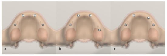
Life, Free Full-Text

Biomechanical effect of implant design on four implants supporting mandibular full-arch fixed dentures: In vitro test and finite element analysis - ScienceDirect

PDF) Stress patterns on implants in prostheses supported by four or six implants: a three-dimensional finite element analysis

Biomechanical comparison of different prosthetic materials and posterior implant angles in all-on-4 treatment concept by three-dimensional finite element analysis

Full article: Biomechanical comparison of implant inclinations and load times with the all-on-4 treatment concept: a three-dimensional finite element analysis
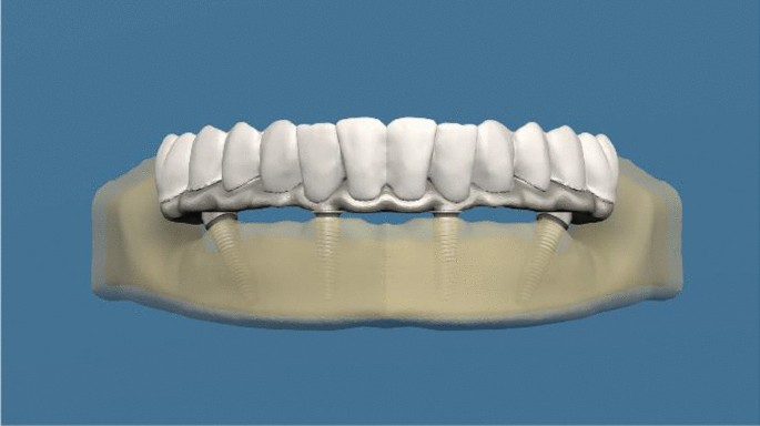
Comparison of stresses in monoblock tilted implants and conventional angled multiunit abutment-implant connection systems in the all-on-four procedure, BMC Oral Health

Effects of Different Positions and Angles of Implants in Maxillary Edentulous Jaw on Surrounding Bone Stress under Dynamic Loading: A Three-Dimensional Finite Element Analysis

Evaluation of two treatment concepts of four implants supporting fixed prosthesis in an atrophic maxilla: finite element analysis, BMC Oral Health

PDF) Biomechanical Comparison of Asymmetric Implant Configurations for All -on-Four Treatment Using Three-Dimensional Finite Element Analysis
Recomendado para você
-
 Strength properties (N/mm 2 ), elastic modulus (N/mm 2 ) and density01 janeiro 2025
 -
![PDF] Full-Range Stress–Strain Curves for Aluminum Alloys](https://d3i71xaburhd42.cloudfront.net/387878655d07c55f809ded7bd8167743a3077065/26-Figure15-1.png) PDF] Full-Range Stress–Strain Curves for Aluminum Alloys01 janeiro 2025
PDF] Full-Range Stress–Strain Curves for Aluminum Alloys01 janeiro 2025 -
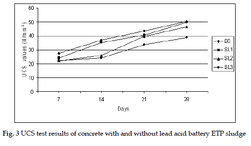 UTILIZATION OF INDUSTRIAL EFFLUENT TREATMENT PLANT (ETP) SLUDGE AS PARTIAL REPLACEMENT FOR CEMENT IN CONCRETE01 janeiro 2025
 -
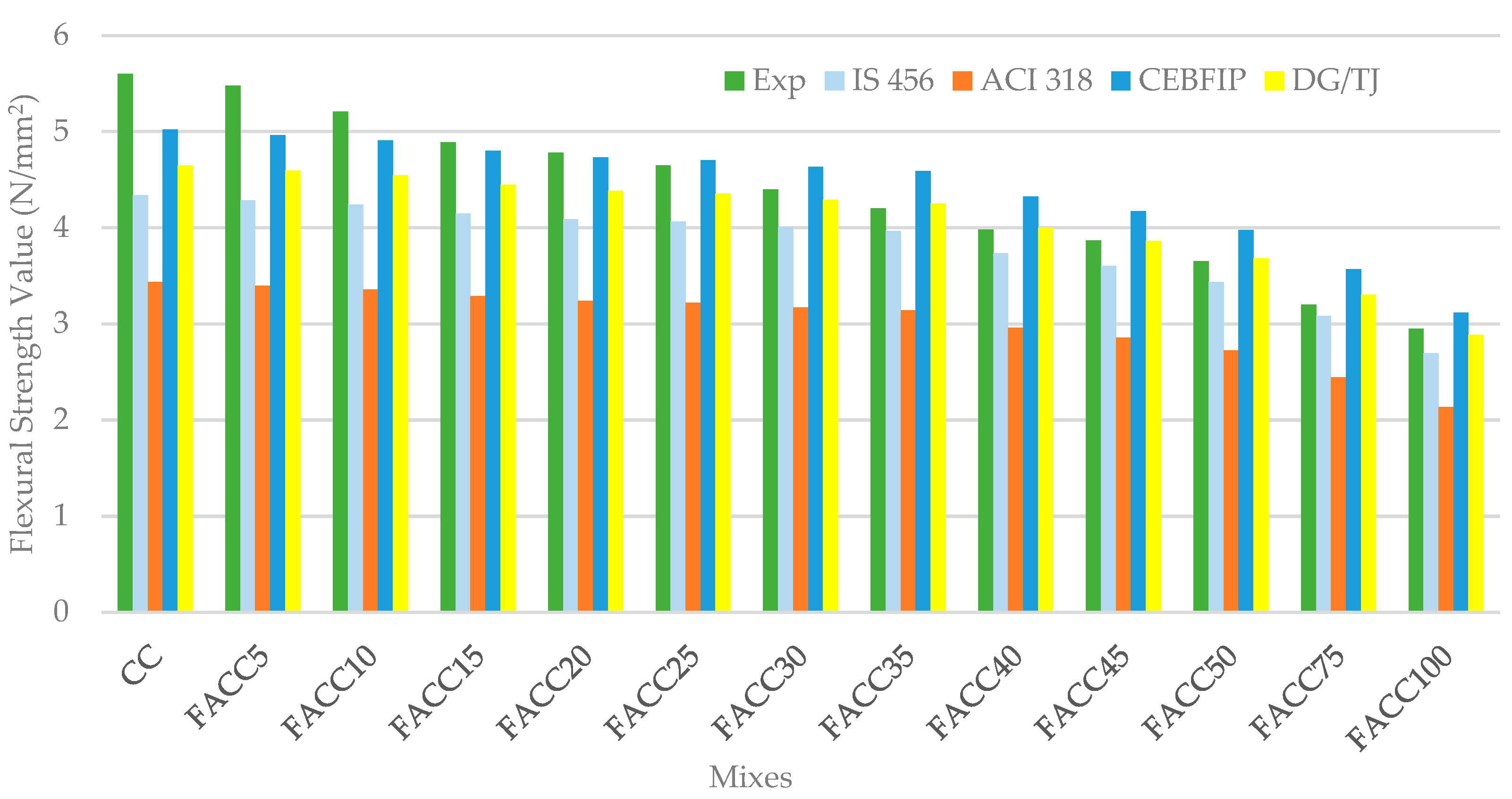 Buildings, Free Full-Text01 janeiro 2025
 -
![PDF] Impact of the Wing Sweep Angle and Rib Orientation on Wing Structural Response for Un-Tapered Wings](https://d3i71xaburhd42.cloudfront.net/55a5fcc0947e561e6ab8fdb8bf45d7e9adc8b110/18-Figure19-1.png) PDF] Impact of the Wing Sweep Angle and Rib Orientation on Wing Structural Response for Un-Tapered Wings01 janeiro 2025
PDF] Impact of the Wing Sweep Angle and Rib Orientation on Wing Structural Response for Un-Tapered Wings01 janeiro 2025 -
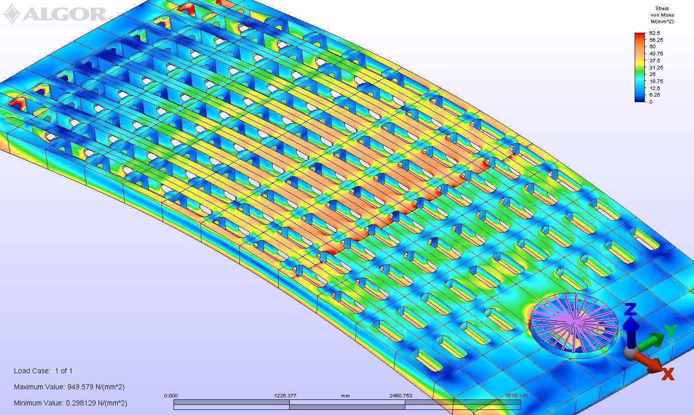 Finite Element Analysis (FEA) • Gregory C. Marshall Naval Architect Ltd. • Gregory C. Marshall Naval Architect Ltd.01 janeiro 2025
 -
 A beam of L meters span simply supported at end carries a central load W. The overall depth of beam section is 300 mm with horizontal flanges each of 200 mm x01 janeiro 2025
 -
 Sterling Seal and Supply (STCC) TF1863.01512X12 Tan with Green Tint TerMica Teadit Extreme Heat Resistant Mica, 1/64 Thick, Sheet Size 12 x 12: : Industrial & Scientific01 janeiro 2025
 -
 i) Draw the shear force and bending moment diagrams. (ii) Label and locate the maximum values in terms of P, a, b and L01 janeiro 2025
 -
![Solved] Principal stresses at a point are 80 N/mm2 and 40 N/mm2, bot](https://storage.googleapis.com/tb-img/production/20/05/F3_A.M_Madhu_05.05.20_D%201.png) Solved] Principal stresses at a point are 80 N/mm2 and 40 N/mm2, bot01 janeiro 2025
Solved] Principal stresses at a point are 80 N/mm2 and 40 N/mm2, bot01 janeiro 2025
você pode gostar
-
Coleção Dvds Filmes - Brinquedo Assassino ( Chucky )01 janeiro 2025
-
 Ovo Surpresa - Galinha Pintadinha - MP Brinquedos01 janeiro 2025
 -
 My Life As A Teenage Robot Jenny Vector - Free Transparent PNG01 janeiro 2025
 -
 HGLG11: O que saber antes de investir nesse fundo imobiliário01 janeiro 2025
 -
 The Woman in the Window: A Novel01 janeiro 2025
 -
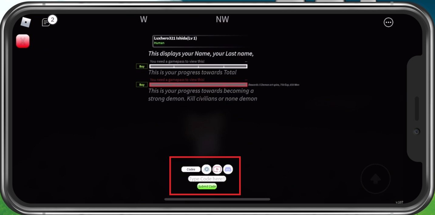 Project Slayers - How To Enter Codes on PC and Mobile (+ Rare Codes) — Tech How01 janeiro 2025
 -
 Beginner Tips For Shadow Warrior 301 janeiro 2025
 -
 13 Jogos Mídia Digital - Xbox 360 Original01 janeiro 2025
 -
Koraidon ex Pokemon (2023) Japanese Scarlet ex - 106/78 CGC 10 PRISTINE01 janeiro 2025
-
 KYLIAN MBAPPÉ Figurinhas da copa, Futebol, Desenho toy story01 janeiro 2025
